

Dual Motor PWM Control with Forward and Reverse Over WiFi
")
Understanding how to control a motor with a PWM signal is a very good skill to add to your toolkit as the same tools can be used in any application where you need to control a voltage.
Todays tutorial starts of with providing a understanding of what PWM is and how to use it to control speed, brightness and general voltage control. Then we will look at how to implement it in code for a MCU that does not have a native PWM output, which will assist in understanding how it works and how you can modify your custom code to suit other applications.
Shifting our focus to the ESP8266, we will look at how to use Arduino commands to utilise the native PWM capability on various pins. Because the ESP8266 cannot directly drive a motor, a H-Bridge motor controller will be introduced to allow the final step of controlling two motors in forward and reverse over WiFi.
What is PWM
PWM stands for Pulse Width Modulation and is a method of creating a variable average DC voltage from a digital output.
It works by changing the ratio of the high pulse to low pulse width over a known time period (T) and is stated in terms of duty cycle (D) as a percentage. As shown in Figure 1, the larger the duty cycle (the high portion), the higher the average voltage and subsequently, the brighter the LED or faster the motor. To achieve this in code is very easy as you simply need to turn an output on and off at known intervals as is explained below. However, whereever possible, I recommend using native PWM if the MCU has one.

Create a PWM Function
Creating a PWM function in code demonstrates how it works by using a FOR loop and an IF THEN ELSE statement. By counting from 0-100 in the loop and comparing the value of dutyCycle (0-100%) to the current position in the loop, the output pin will be on for the percentage passed. The circuit in Figure 2 shows the wiring to match the code below, with R2 setting the PWM duty cycle to dim the LED. Note that the ADC on A0 can only read to 1v dc so a voltage divide of R2 and R3 ensures the voltage is near this maximum value.
The Fritzing and Arduino files can be downloaded from this link
PWM Function
void PWM(byte dutyCycle, byte PWMpin)
{
/* Receives a PWM value from 0-100% and the ouptup pin to control.
* Drived the pin with a duty cycle of high/low to control the average voltage
*/
  byte i = 0;

  for (i; i < 100; i++)
  {
    if (i <= dutyCycle)
    {
      digitalWrite(PWMpin,HIGH);
    }
    else
    {
      digitalWrite(PWMpin,LOW);
    }
  }
}
The downside to performing PWM with this function is your program spends most of its time stuck in the FOR loop, limiting the processors’ ability to execute other code.
As such, I would only recommend this as an alternative to the other options offered below.
Loop and Setup functions
#define LEDanode D5
#define LEDcathode D6

void setup()
{
  pinMode(LEDanode, OUTPUT);
  pinMode(LEDcathode, OUTPUT);
 }

void loop()
{
  int16_t speed;
  speed = analogRead(A0);              // Read the value on Pin A0 (Range 0-1vdc = 0-1024)
  speed = map(speed, 0, 1024, 0, 100); // Scale ADC to 0-100% range

  digitalWrite(LEDcathode, LOW);
  PWM(speed, LEDanode); // Call the PWM function
}
ESP8266 Native PWM
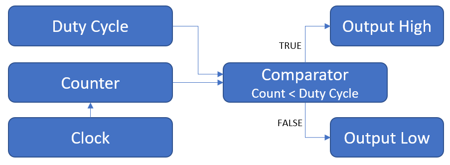
A native PWM is one done by the hardware of the processor rather than the software, which means it requires far less CPU time than the code above.
The PWM in the ESP8266 and most other MCU’s operates as shown in the simplified block diagram, where a counter counts the pulses from a clock and the comparator compares the count to the duty cycle just like we did in the FOR loop above. If it is less than, the output pin is set high and if greater than, it is low.
The way we tell the pins to do this is via the analogWrite(pin, value) and analogWriteFreq(frequency) instructions.
To control pin D5 as above we use analogWrite(D5, value) where the value is in the range of 0 – 1023. This range can be changed to a different value such as 0-100 using the analogWriteRange(new_range). Note that most Arduino boards only have a range of 0-254 compared with the 0-1023 of the ESP8266 and have a different command for setting the resolution analogWriteResolution()
The default period for the PWM signal is 1KHz but if the processor is working hard, this may drop. You can manually reduce this using the analogWriteFreq(frequency) to be in the range of 100 – 1000 Hz, which will reduce the load on the processor.
As can be seen in the code, this basically reduces the PWM function to one instruction on line 16.
The pins that support PWM on the ESP8266 are all GPIO except D0 (GPIO16). However, the following have special functions during boot and will go high, possibly causing unexpected results in your external circuits so should be avoided if possible. D0 (GPIO16), D4 (GPIO2), RX (GPIO3) & TX (GPIO1).
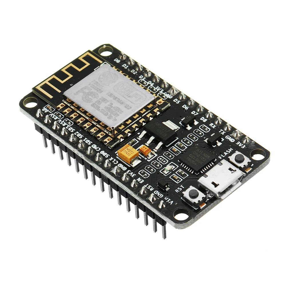
The official pinout diagram can be found on Github for the NodeMCU
Native PWM Function
void setup()
{
pinMode(LEDanode, OUTPUT);
pinMode(LEDcathode, OUTPUT);
analogWriteRange(100); // set the PWM range to represent 0-100%
analogWriteFreq(1000); // reduce the PWM freq to reduce load on CPU
}
void loop()
{
int16_t speed;
speed = analogRead(A0); // Read the value on Pin A0 (Range 0-1vdc = 0-1024)
speed = map(speed, 0, 1024, 0, 100); // Scale ADC to 0-100% range
digitalWrite(LEDcathode, LOW); // this line is not needed but will be used later
analogWrite(LEDanode,speed);
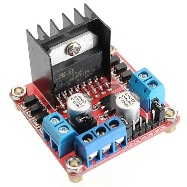
}Motor Controllers
The motor controller is an interface between the low voltage, low current output of the microcontroller and the higher power requirements of the motor(s). It has no smarts about it and only responds to a high or low on its inputs, converting that to a higher voltage output.
You may have noticed earlier in the PWM code that we were doing a digitalWrite(LEDcathode, LOW), which would be the same as connecting one side of the LED to ground. We will now use that to change motor direction, initially shown on a 2 LED’s. Green for forward and red for reverse.
Changing the sketch as shown will cause one LED to turn on for a second and then the other, both with PWM control.
The way a H-bridge motor controller works is by applying a small amount of current to its input in one polarity will result in a matching polarity at the higher voltage outputted to drive the motor. Reversing the polarity of the input reverses the polarity of the output and hence changes the motor direction. The PWM input is also followed on the output, resulting in a change in motor speed.

Native PWM Function with Direction Change
void loop()
{
int16_t speed;
speed = analogRead(A0); // Read the value on Pin A0 (Range 0-1vdc = 0-1024)
speed = map(speed, 0, 1024, 0, 100); // Scale ADC to 0-100% range
digitalWrite(LEDcathode, LOW); // Forward voltage direction
analogWrite(LEDanode, speed);
delay(1000);
digitalWrite(LEDanode, LOW); // Reverse voltage direction
analogWrite(LEDcathode, speed);
delay(1000);
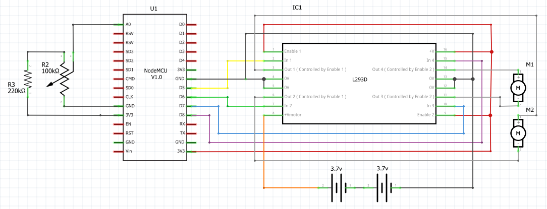
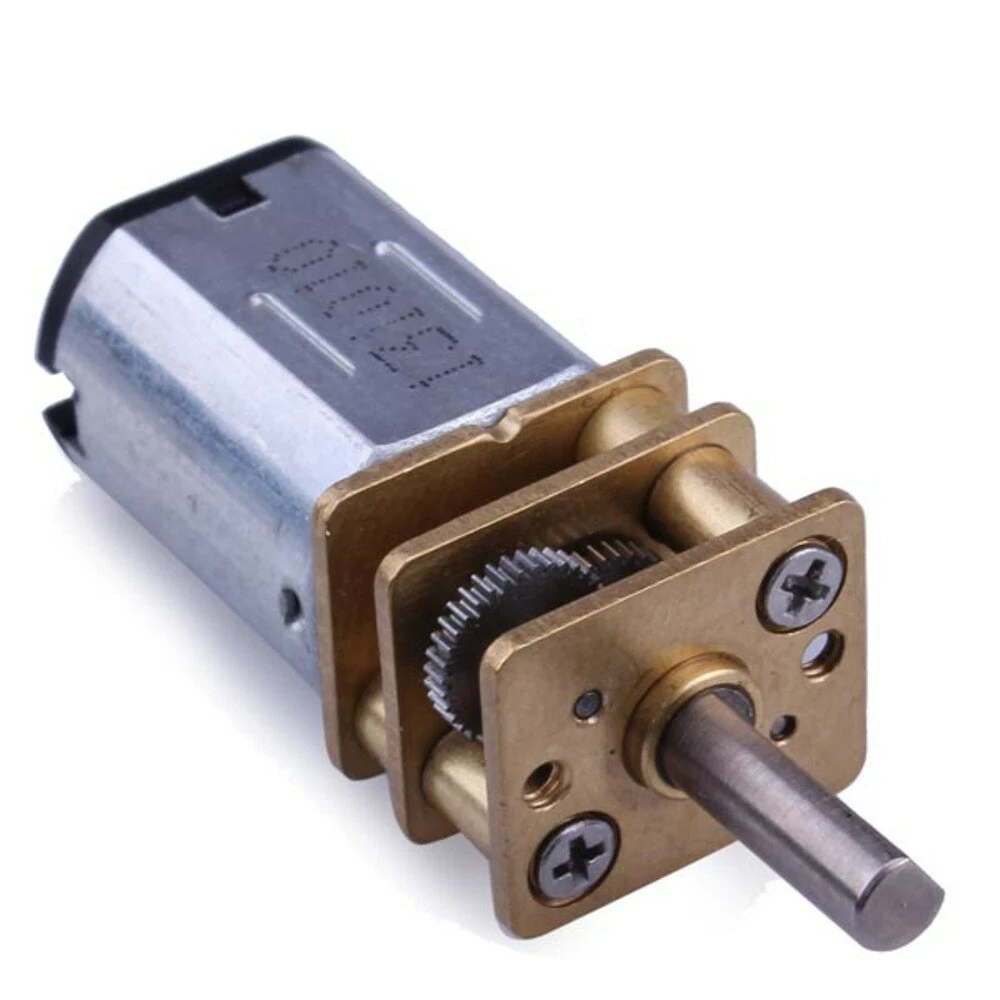
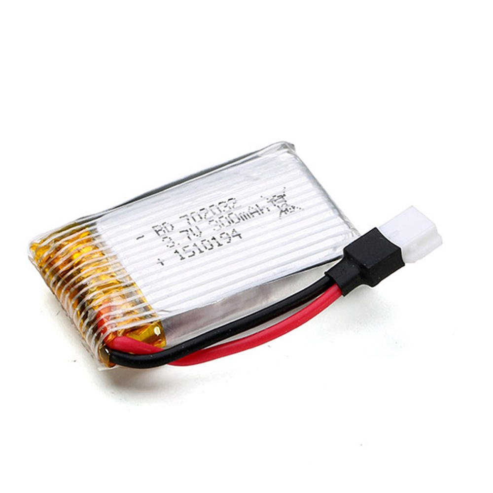
}Moving from LED’s to the H-bridge motor controller is just a case of replacing the connections to the LED’s with that of the controller. In the schematic below, I have jumped ahead and shown the configuration for two motors but if you just want one, just connect D5 and D6 to IN1 and IN2. The motor I am using are 6v DC and to achieve this, I have connected 2X 3.7v LiPo batteries in series but you could use an alternative power source with voltages as high as 35 volts depending on the particular motor controller you choose. I use a larger controller for prototyping because it’s more tolerant of my mistakes and easy to connect to. 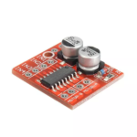 However, I typically use something much smaller for this size motor such as the one pictured here.
Before moving onto the WiFi code, test the motors are wired correctly and operate as expected with the following code which will drive the motors, changing direction at 1-second intervals.
The motorControl function changes the pin states to control forward, reverse, left and right.
Motor control function
void motorControl(motor_t side, motorDirection_t direction, int16_t speed)
{
  if (side == RIGHT) //Right Motor
  {
    if (direction == FORWARD)
    { // Forward
      analogWrite(motorA1, speed);
      digitalWrite(motorA2, LOW);
    }
    else
    { // Reverse
      analogWrite(motorA2, speed);
      digitalWrite(motorA1, LOW);
    }
  }
  else if (side == LEFT)  // Left Motor
  {
    if (direction == FORWARD)
    { // Forward
      analogWrite(motorB1, speed);
      digitalWrite(motorB2, LOW);
    }
    else
    { // Reverse
      analogWrite(motorB2, speed);
      digitalWrite(motorB1, LOW);
    }
  }
}
Setup and Loop for motor control
#define motorA1 D5
#define motorA2 D6
#define motorB1 D7
#define motorB2 D8

typedef enum
{
  LEFT = 0,
  RIGHT = 1
} motor_t;
typedef enum
{
  FORWARD = 0,
  REVERSE = 1
} motorDirection_t;

void setup()
{
  Serial.begin(115200);
  pinMode(motorA1, OUTPUT);
  pinMode(motorA2, OUTPUT);
  pinMode(motorB1, OUTPUT);
  pinMode(motorB2, OUTPUT);
  analogWriteRange(100); // set the PWM range to represent 0-100%
  analogWriteFreq(1000); // reduce the PWM freq to reduce load on CPU
}

void loop()
{
  int16_t speed;
  speed = analogRead(A0);              // Read the value on Pin A0 (Range 0-1vdc = 0-1024)
  speed = map(speed, 0, 1024, 0, 100); // Scale ADC to 0-100% range

  motorControl(RIGHT, FORWARD, speed); // Right Forward direction
  delay(1000);
  motorControl(RIGHT, REVERSE, speed); // Right Reverse direction
  delay(1000);
  motorControl(LEFT, FORWARD, speed); // Left Forward direction
  delay(1000);
  motorControl(LEFT, REVERSE, speed); // Left Reverse direction
  delay(1000);
}
WiFi Control Interface
While I was writing this post, it became apparent that the WiFi control was a tutorial in itself. So rather than include it here, I will create a new post and link to it shortly.
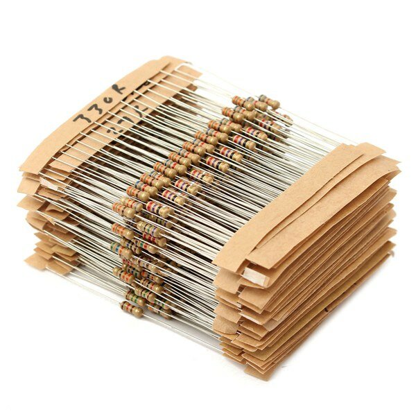
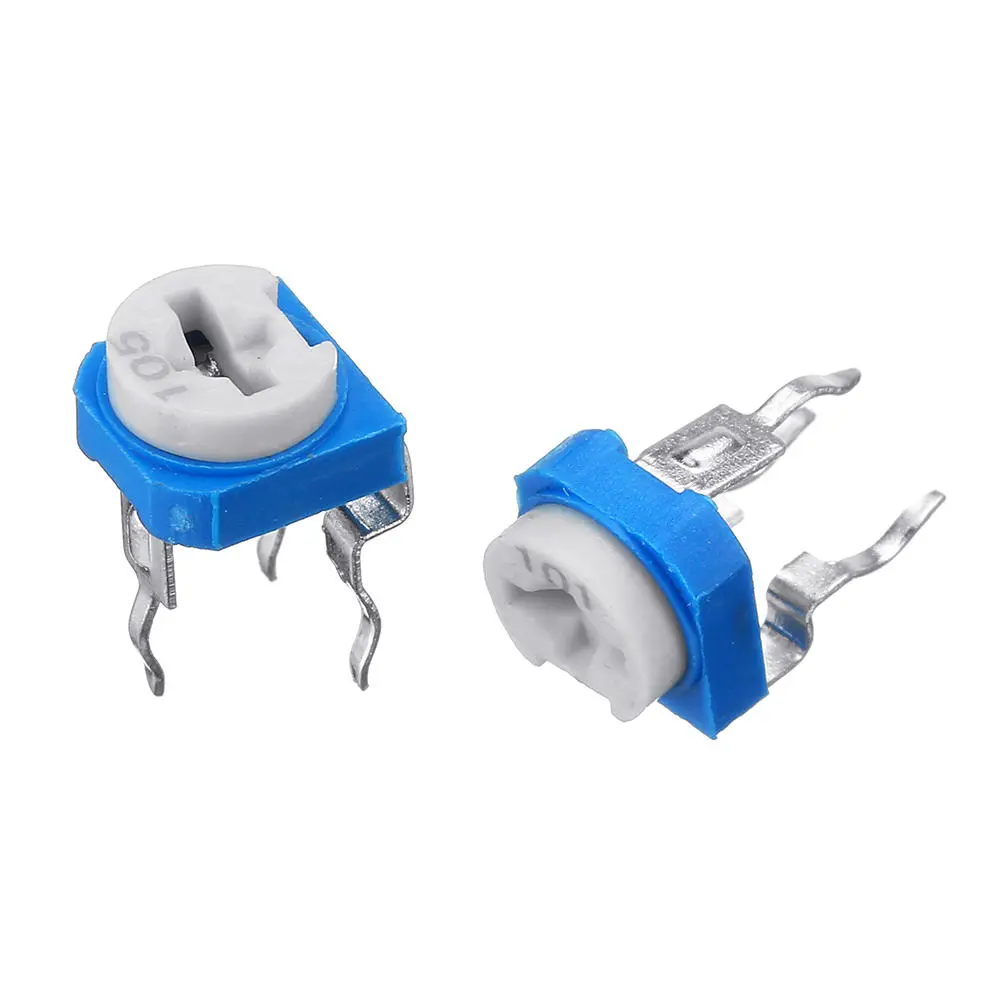
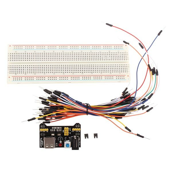
Parts List
Links to all parts used in this tutorial are listed below from the distributor Banggood.
0 Comments